Content Status
Type
Linked Node
Structure and Function of the CBNAAT Module
Learning ObjectivesDiscuss the modular structure of the GeneXpert Platform.
Describe the various parts of the Module.
Open configuration options
The CBNAAT module contains components that enable automated sample processing in the cartridge, and filling of the tube with the sample-reagent mixture for Polymerase Chain Reaction (PCR), followed by PCR amplification and detection.
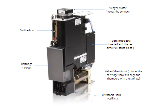
The structure of the CBNAAT module is described below and shown in Figure 1:
- Syringe pump drive or plunger motor: Dispenses fluids into the different cartridge chambers
- I-CORE module: Performs PCR amplification and detection
- A cartridge loading and unloading mechanism ensures the proper movement of the cartridge in the instrument
- Reaction/PCR tube: Enables rapid thermal cycling and optical excitation and detection of the tube contents. The reaction tube is automatically inserted into the I-CORE module (hardware for PCR amplification and fluorescence detection) when the cartridge is loaded into the instrument.
- Valve drive: Rotates the cartridge valves to align the chambers with the syringe
- Ultrasonic horn: Lyses the sample

Figure 1: Structure of the CBNAAT module
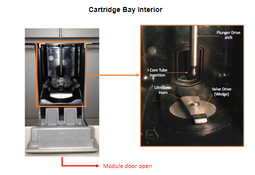
The interior region of the cartridge insertion site also called cartridge bay and is shown in Figure 2.

Figure 2: Interior of the Cartridge Bay
Mode of Operation of the CBNAAT Module
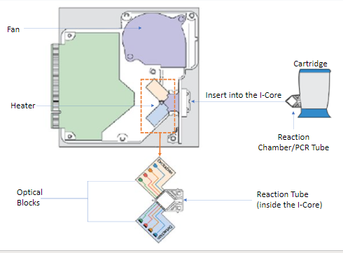
- The Intelligent Cooling/Heating Optical Reaction (I-CORE) module is the hardware component, within each instrument module, that performs PCR amplification and, fluorescence detection.
- As part of the cartridge load process, the PCR tube is inserted into the ICORE module.
- As the test starts, the sample and reagent mixture are pushed from the cartridge, into the PCR tube.
- During the amplification process, the ICORE heater heats up and the fan cools down the reaction tube contents.
Within the I-CORE, there is an optical system composed of two blocks: A six colour excitor and detector block excite the dye molecules, and detect the fluorescence emitted.

Figure 3: Mode of operation of the CBNAAT module
Resources
Kindly provide your valuable feedback on the page to the link provided HERE
Content Creator
Reviewer
Target Audience
- Log in to post comments